Smith Chart With Admittance
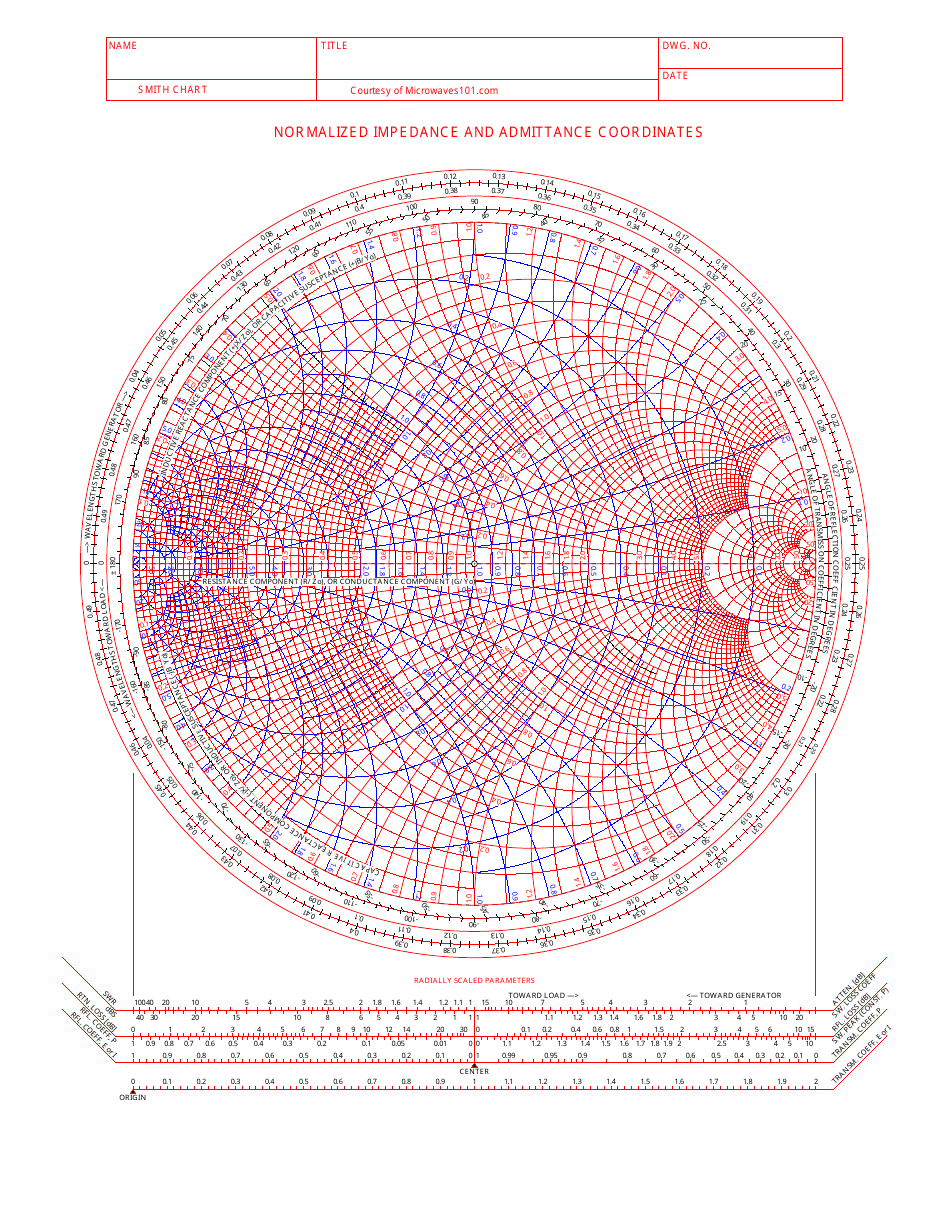
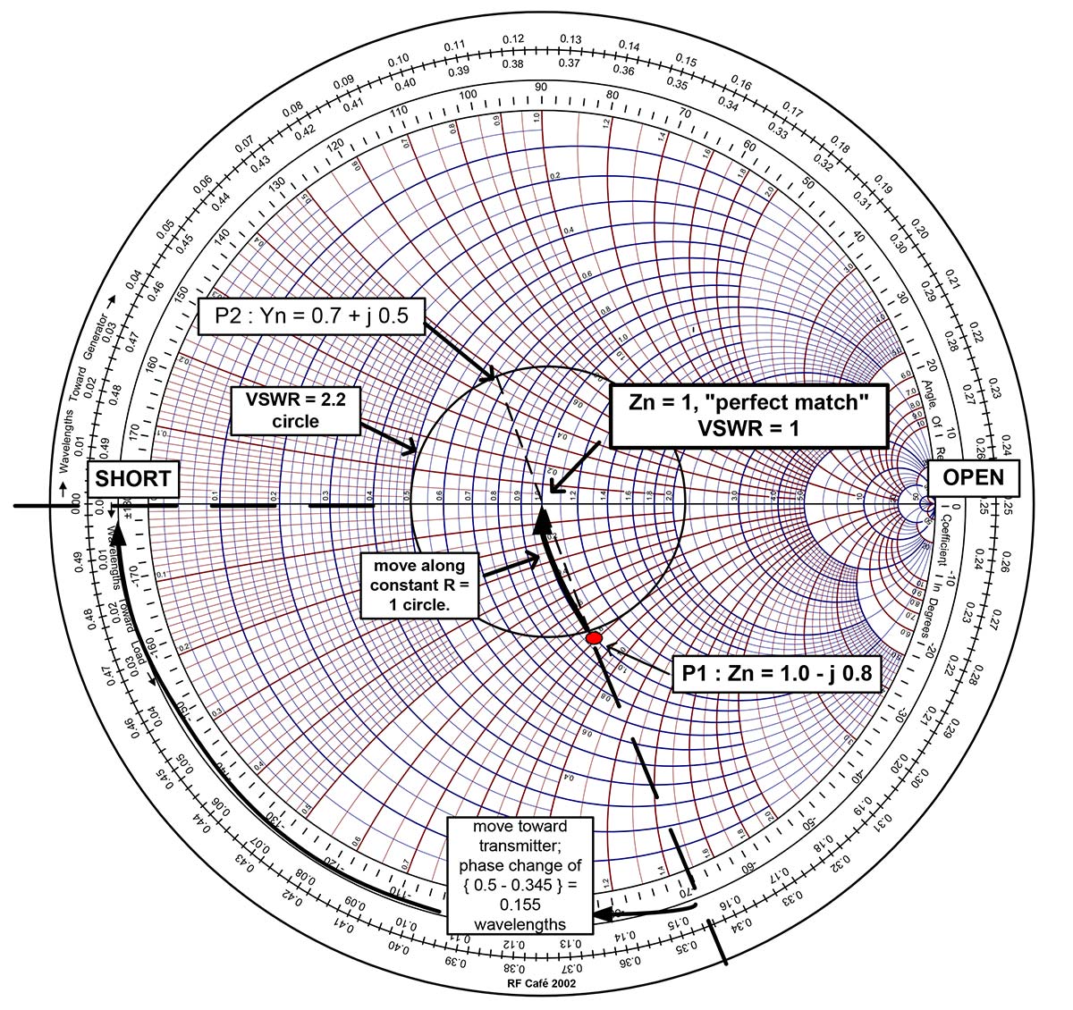
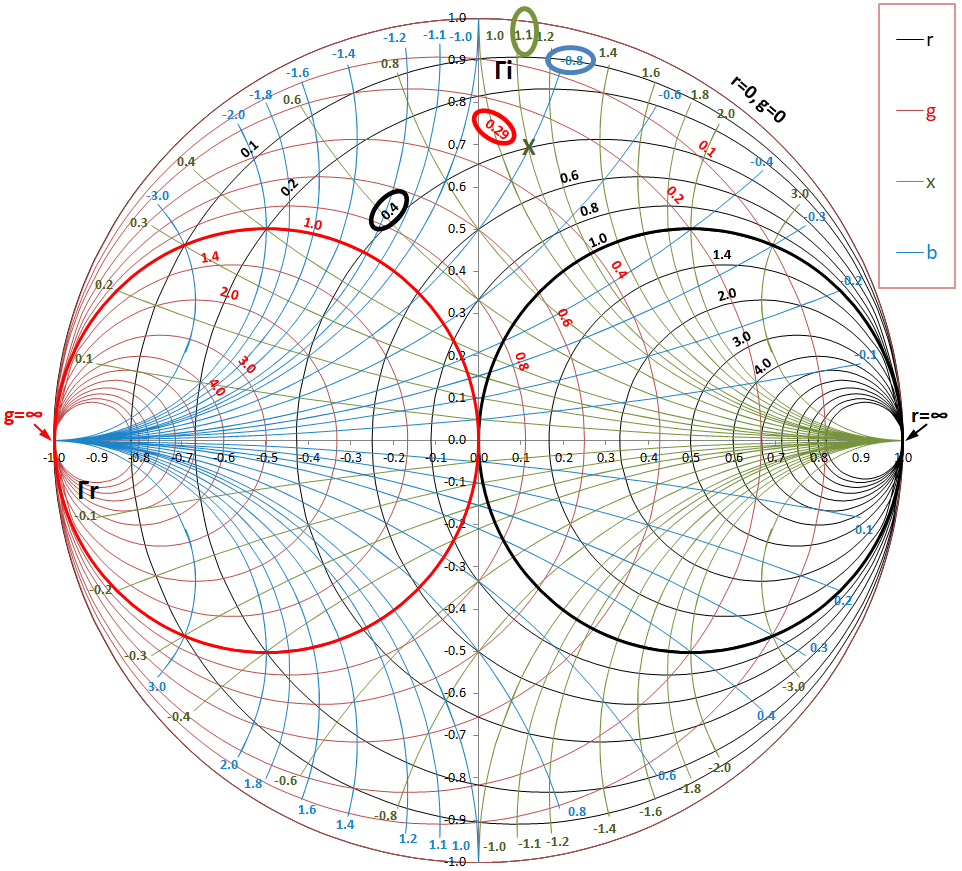
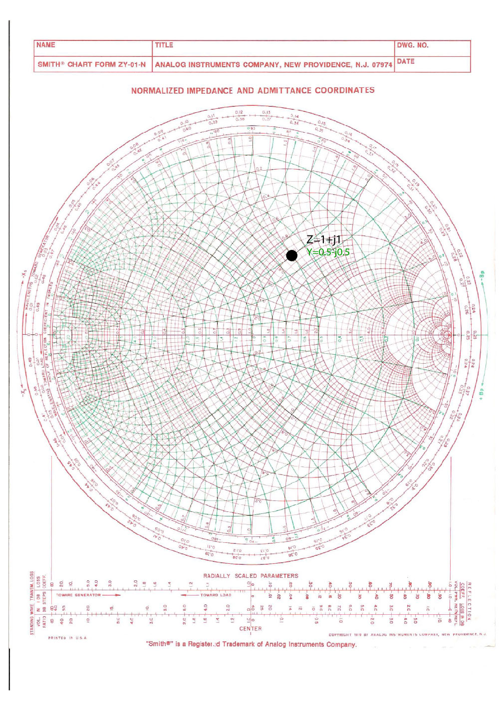
Smith Chart With Admittance - The admittance smith chart has loci for discrete constant susceptances ranging from \(−∞\) to \(∞\), and for discrete constant conductance ranging from \(0\) to \(∞\), see figure \(\pageindex{9}\). Web the smith chart can be used to simultaneously display multiple parameters including impedances, admittances, reflection coefficients, scattering parameters, noise figure circles, constant gain contours and regions for unconditional stability. For example, the impedance z = 0.5 + j2 is marked as point a in the above figure. Click anwhere inside the chart to see the corresponding circles. In the next section, we will learn to use impedance/admittance (z/y) smith chart, where both impedance and admittance circles are shown. Web the smith chart provides a graphical representation of γ that permits the determination of quantities such as the vswr or the terminating impedance of a device under test (dut). 2/17/2010 example admittance calculations with the smith chart 3/9 jim stiles the univ. Web we can use this smith chart to read off the values for the impedance, and reflection coefficient. The admittance smith chart has loci for discrete constant susceptances ranging from \(−∞\) to \(∞\), and for discrete constant conductance ranging from \(0\) to \(∞\), see figure \(\pageindex{7}\). A horizontal line through the center of the. L=16 26+ in terms of its. Web this free online interactive smith chart tool is a calculator which can help you design matching networks and obtain maximum power transfer between your source and load. A less dense form is shown in figure \(\pageindex{8}\)(a). Enter load and characteristic impedances to calculate vswr and reflection coeffecients. It is made of circles that. Web a smith chart is developed by examining the load where the impedance must be matched. The admittance smith chart has loci for discrete constant susceptances ranging from \(−∞\) to \(∞\), and for discrete constant conductance ranging from \(0\) to \(∞\), see figure \(\pageindex{9}\). What is a smith chart? These graphs are used for visualizing the impedance at any point. Web smith chart can be used to display several parameters including; That is, we are looking at the impedance of an antenna, or load (z_l). This video describes how to. Web 3.4.2 admittance smith chart. The admittance smith chart has loci for discrete constant susceptances ranging from \(−∞\) to \(∞\), and for discrete constant conductance ranging from \(0\) to \(∞\),. Web smith chart can be used to display several parameters including; Web the smith chart is made up of multiple circles, and segments of circles arranged in a way to plot impedance values in the form of r ± jx (fig. L=16 26+ in terms of its. Web the moebius transform that generates the smith chart provides also a mapping. We can calculate this complex value—or we can use a smith chart! Recall that on the standard or impedance smith chart, the circles and curves related to constant resistance and constant reactance. Enter load and characteristic impedances to calculate vswr and reflection coeffecients. Web impedance smith charts also known as z charts are the polar graphs that show the normalized. Web we can use this smith chart to read off the values for the impedance, and reflection coefficient. This tool is javascript so it works on windows, mac, ios,. Web smith chart can be used to display several parameters including; That is, we are looking at the impedance of an antenna, or load (z_l). These graphs are used for visualizing. Web the moebius transform that generates the smith chart provides also a mapping of the complex admittance plane (y = 1 z or normalized y = 1 z) into the same chart: Web a smith chart is developed by examining the load where the impedance must be matched. Web the smith chart can be used to simultaneously display multiple parameters. L=16 26+ in terms of its. In the next section, we will learn to use impedance/admittance (z/y) smith chart, where both impedance and admittance circles are shown. Web the smith chart can be used to simultaneously display multiple parameters including impedances, admittances, reflection coefficients, scattering parameters, noise figure circles, constant gain contours and regions for unconditional stability. How much is. Γ = − y −1 y +1 = − y −y0 y +y0 = − 1/z −1/z0 1/z +1/z0 = z −z0 z +z0 = z −1 z +1 (6) using this transformation, the result is the same chart, only mirrored at the. Move the mouse around the chart. Web the smith chart can be used to simultaneously display multiple. It is made of circles that represent different values. We can calculate this complex value—or we can use a smith chart! Impedances, admittances, reflection coefficients, scattering parameters, noise figure circles, constant gain contours and regions for unconditional stability, and mechanical vibrations analysis, all at the same time. In our case, \[y_{0} = \frac{1}{z_{0}} = \frac{1}{50} = 0.02\] Web a smith. It uses a bilinear moebius transformation, projecting the complex impedance plane onto the complex γ plane: A less dense form is shown in figure \(\pageindex{8}\)(a). L=16 26+ in terms of its. These graphs are used for visualizing the impedance at any point on the transmission line or any input in the systems of the antenna. Web 8.3.2 admittance smith chart. In our case, \[y_{0} = \frac{1}{z_{0}} = \frac{1}{50} = 0.02\] Recall that on the standard or impedance smith chart, the circles and curves related to constant resistance and constant reactance. First, we express the load z.j. It is made of circles that represent different values. How much is that stub worth? We can calculate this complex value—or we can use a smith chart! 2/17/2010 example admittance calculations with the smith chart 3/9 jim stiles the univ. In the next section, we will learn to use impedance/admittance (z/y) smith chart, where both impedance and admittance circles are shown. Web impedance smith charts also known as z charts are the polar graphs that show the normalized line impedance in the complex reflection coefficient plane. This video describes how to. Web the moebius transform that generates the smith chart provides also a mapping of the complex admittance plane (y = 1 z or normalized y = 1 z) into the same chart: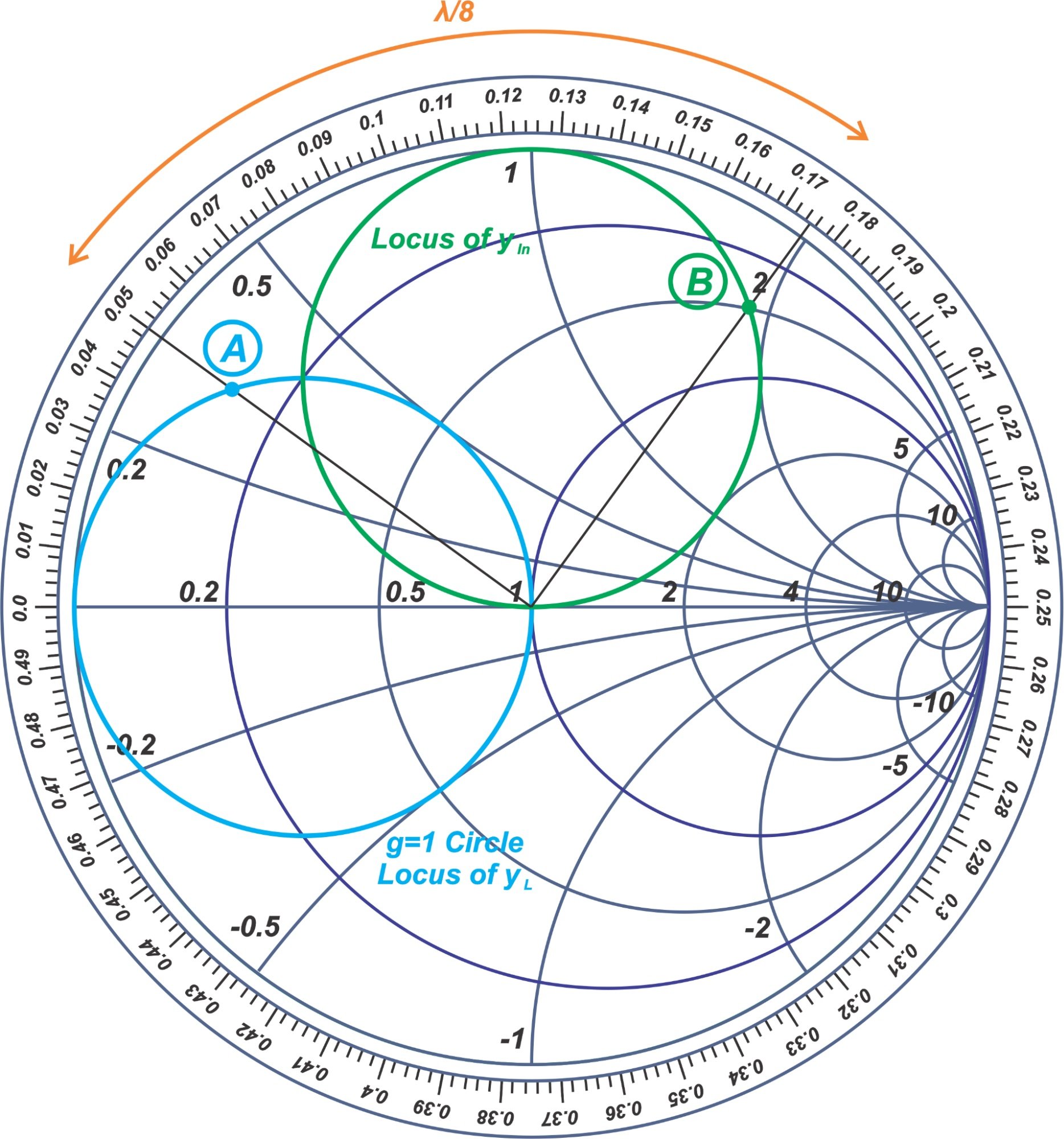
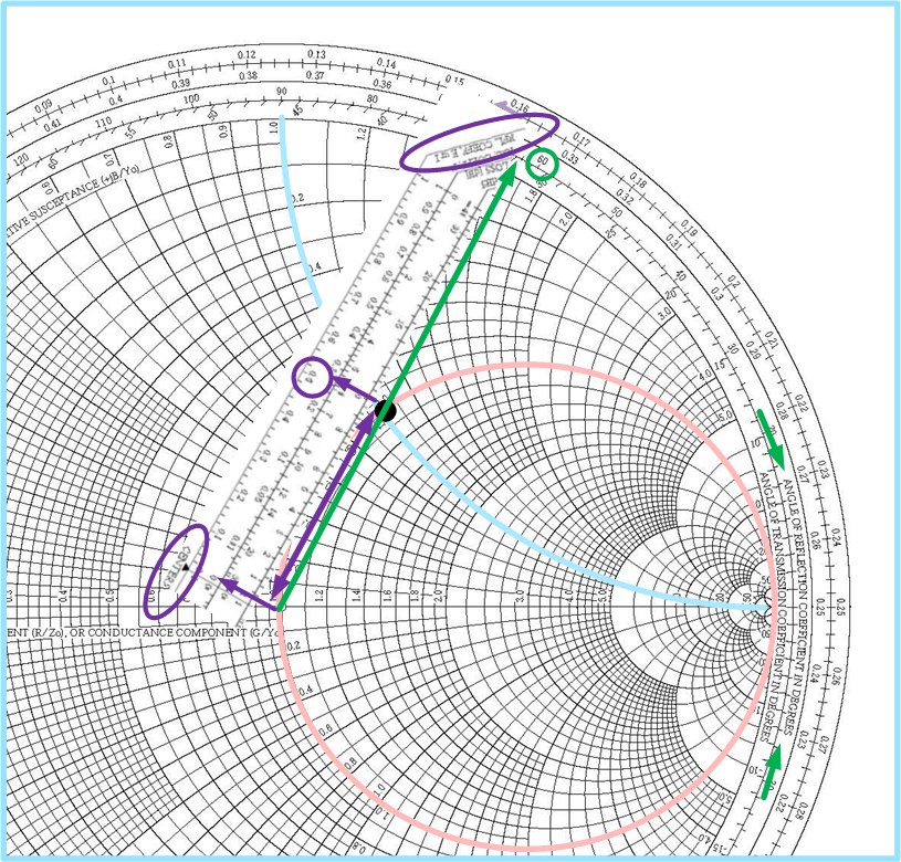
Learn Stub Tuning With a Smith Chart Technical Articles
Normalized Impedance and Admittance Coordinates Smith Chart Download
Free Admittance Smith Chart PDF 956KB 1 Page(s)
how to use a smith chart Jude Misaid
Impedance and Admittance on Smith Chart Ximera

Impedance Matching by Using Smith Chart A StepbyStep Guide, Part II

Free Admittance Smith Chart PDF 956KB 1 Page(s)
Impedance Matching by Using Smith Chart A StepbyStep Guide, Part II
Impedance and Admittance on Smith Chart Ximera
What is Smith Chart and how to use it for Impedance Matching
Enter Load And Characteristic Impedances To Calculate Vswr And Reflection Coeffecients.
That Is, We Are Looking At The Impedance Of An Antenna, Or Load (Z_L).
Web The Smith Chart Can Be Used To Simultaneously Display Multiple Parameters Including Impedances, Admittances, Reflection Coefficients, Scattering Parameters, Noise Figure Circles, Constant Gain Contours And Regions For Unconditional Stability.
9.1K Views 3 Years Ago Emp Microwave Engineering.
Related Post: