Oring Groove Dimensions Chart
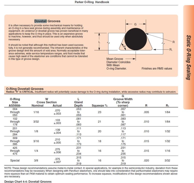
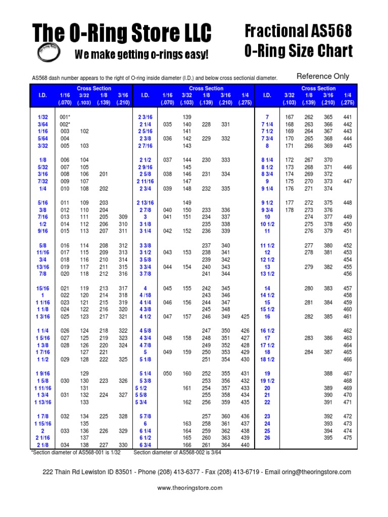
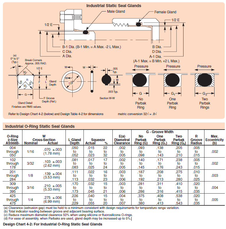
Oring Groove Dimensions Chart - In special applications, for example in the semiconductor industry, deviation from these recommendations may be necessary. Web below, four standard application groove design guidance tables are presented along with dimensional reference drawings. The minimum and maximum conditions should also be checked. The first table is for industrial face or flange seals. For designing systems which contain internal pressure, like the example below, the groove's outside diameter (od) is primary, and the groove's width then determines the inside diameter. • nitrile nbr 70 and 90 shore a, The second table is for static industrial radial applications. We have included static, dynamic, and pneumatic applications. The guidelines are for the nominal condition. Contact us for assistance or samples click here and contact us today to receive a quote or if you have any questions regarding sizing. Gland detail finishes are rms values. In special applications, for example in the semiconductor industry, deviation from these recommendations may be necessary. For axial, radial and flange applications. Depth (= gland depth) i.d. We have included static, dynamic, and pneumatic applications. Web o'ring groove dimensions for static and dynamic operation. The second table is for static industrial radial applications. We have included static, dynamic, and pneumatic applications. The minimum and maximum conditions should also be checked. For axial, radial and flange applications. The calculator takes all relevant parameters into account like: For axial, radial and flange applications. For designing systems which contain internal pressure, like the example below, the groove's outside diameter (od) is primary, and the groove's width then determines the inside diameter. Web o'ring groove dimensions for static and dynamic operation. The first table is for industrial face or flange. In special applications, for example in the semiconductor industry, deviation from these recommendations may be necessary. The minimum and maximum conditions should also be checked. Gland detail finishes are rms values. • nitrile nbr 70 and 90 shore a, Contact us for assistance or samples click here and contact us today to receive a quote or if you have any. The third table is for dynamic industrial reciprocating applications. The second table is for static industrial radial applications. The minimum and maximum conditions should also be checked. For designing systems which contain internal pressure, like the example below, the groove's outside diameter (od) is primary, and the groove's width then determines the inside diameter. The first table is for industrial. The second table is for static industrial radial applications. Depth (= gland depth) i.d. Gland detail finishes are rms values. Contact us for assistance or samples click here and contact us today to receive a quote or if you have any questions regarding sizing. Simple selection tool to easily order online today. Gland detail finishes are rms values. The first table is for industrial face or flange seals. The second table is for static industrial radial applications. For axial, radial and flange applications. Contact us for assistance or samples click here and contact us today to receive a quote or if you have any questions regarding sizing. Most of these sizes are readily available from eriks stock in: The first table is for industrial face or flange seals. Contact us for assistance or samples click here and contact us today to receive a quote or if you have any questions regarding sizing. Depth (= gland depth) i.d. In special applications, for example in the semiconductor industry, deviation. The third table is for dynamic industrial reciprocating applications. Gland detail finishes are rms values. The minimum and maximum conditions should also be checked. Simple selection tool to easily order online today. For designing systems which contain internal pressure, like the example below, the groove's outside diameter (od) is primary, and the groove's width then determines the inside diameter. For designing systems which contain internal pressure, like the example below, the groove's outside diameter (od) is primary, and the groove's width then determines the inside diameter. Web o'ring groove dimensions for static and dynamic operation. The minimum and maximum conditions should also be checked. Gland detail finishes are rms values. Simple selection tool to easily order online today. The minimum and maximum conditions should also be checked. The third table is for dynamic industrial reciprocating applications. In special applications, for example in the semiconductor industry, deviation from these recommendations may be necessary. Simple selection tool to easily order online today. Web o'ring groove dimensions for static and dynamic operation. The calculator takes all relevant parameters into account like: The first table is for industrial face or flange seals. • nitrile nbr 70 and 90 shore a, For axial, radial and flange applications. For designing systems which contain internal pressure, like the example below, the groove's outside diameter (od) is primary, and the groove's width then determines the inside diameter. Depth (= gland depth) i.d. Web below, four standard application groove design guidance tables are presented along with dimensional reference drawings. Most of these sizes are readily available from eriks stock in: The guidelines are for the nominal condition.
Sae code 61 o ring groove dimensions Knowledge Yuyao Jiayuan
Printable O Ring Size Chart

o ring groove size chart pdf Ranee Ojeda

O Ring Groove Chart

O'ring Sizing Chart

Oring Groove Size Chart

O Ring Groove Size Chart

O Ring Groove Dimensions Chart
Metric O Ring Groove Size Chart Chart Examples

Basic Applications Metric ORing Groove Design Reference
The Second Table Is For Static Industrial Radial Applications.
Gland Detail Finishes Are Rms Values.
Contact Us For Assistance Or Samples Click Here And Contact Us Today To Receive A Quote Or If You Have Any Questions Regarding Sizing.
We Have Included Static, Dynamic, And Pneumatic Applications.
Related Post:

