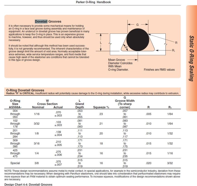
O Ring Groove Size Chart
O Ring Groove Size Chart - Web 10| measurements in millimeters measurements in inches id± ±± csid ±± idcs ±± csid ± 37.60 0.09 39.60 2.40 41.60 44.60 0.44 45.60 47.60 49.60 51.60 2.40 54.60 55.60 0.094 57.60 The info is based on 70 shore a durometer hardness only. The minimum and maximum conditions should also be checked. We have included static, dynamic, and pneumatic applications. The guidelines are for the nominal condition. Most of these sizes are readily available from eriks stock in: Web the following information is a guide for o’ring groove dimensions for both static and reciprocating dynamic applications. Web the three main types of standard groove designs are industrial static also called radial, industrial reciprocating also called dynamic, and face seals also called axial or flange. These correspond to as568a dimensions. O (h ) = mean o.d. The minimum and maximum conditions should also be checked. The info is based on 70 shore a durometer hardness only. The guidelines are for the nominal condition. For more information on shrinkage rates, see the appendix. The minimum and maximum conditions should also be checked. Web 10| measurements in millimeters measurements in inches id± ±± csid ±± idcs ±± csid ± 37.60 0.09 39.60 2.40 41.60 44.60 0.44 45.60 47.60 49.60 51.60 2.40 54.60 55.60 0.094 57.60 The guidelines are for the nominal condition. Generally surface finish for sealing surfaces are as follows… 63rms maximum: Radial and dynamic seals require the presence of a. Most. We have included static, dynamic, and pneumatic applications. Web the three main types of standard groove designs are industrial static also called radial, industrial reciprocating also called dynamic, and face seals also called axial or flange. For more information on shrinkage rates, see the appendix. This requires looking at the dimensionally largest. The guidelines are for the nominal condition. The calculator takes all relevant parameters into account like: Web this chart provides dimensions for standard (an) shrinkage materials only. Most of these sizes are readily. This requires looking at the dimensionally largest. We have included static, dynamic, and pneumatic applications. Most of these sizes are readily. The guidelines are for the nominal condition. Web the three main types of standard groove designs are industrial static also called radial, industrial reciprocating also called dynamic, and face seals also called axial or flange. Web 10| measurements in millimeters measurements in inches id± ±± csid ±± idcs ±± csid ± 37.60 0.09 39.60. These correspond to as568a dimensions. This requires looking at the dimensionally largest. The guidelines are for the nominal condition. Web the following information is a guide for o’ring groove dimensions for both static and reciprocating dynamic applications. Generally surface finish for sealing surfaces are as follows… 63rms maximum: Web the three main types of standard groove designs are industrial static also called radial, industrial reciprocating also called dynamic, and face seals also called axial or flange. Generally surface finish for sealing surfaces are as follows… 63rms maximum: The minimum and maximum conditions should also be checked. For more information on shrinkage rates, see the appendix. Radial and dynamic. Most of these sizes are readily available from eriks stock in: O (h ) = mean o.d. Generally surface finish for sealing surfaces are as follows… 63rms maximum: This requires looking at the dimensionally largest. The minimum and maximum conditions should also be checked. These correspond to as568a dimensions. We have included static, dynamic, and pneumatic applications. Web the following information is a guide for o’ring groove dimensions for both static and reciprocating dynamic applications. For more information on shrinkage rates, see the appendix. The guidelines are for the nominal condition. O (h ) = mean o.d. Web 10| measurements in millimeters measurements in inches id± ±± csid ±± idcs ±± csid ± 37.60 0.09 39.60 2.40 41.60 44.60 0.44 45.60 47.60 49.60 51.60 2.40 54.60 55.60 0.094 57.60 We have included static, dynamic, and pneumatic applications. Generally surface finish for sealing surfaces are as follows… 63rms maximum: The guidelines are. Web the three main types of standard groove designs are industrial static also called radial, industrial reciprocating also called dynamic, and face seals also called axial or flange. The minimum and maximum conditions should also be checked. Most of these sizes are readily. For more information on shrinkage rates, see the appendix. O (h ) = mean o.d. These correspond to as568a dimensions. This requires looking at the dimensionally largest. The info is based on 70 shore a durometer hardness only. Web the following information is a guide for o’ring groove dimensions for both static and reciprocating dynamic applications. Most of these sizes are readily available from eriks stock in: We have included static, dynamic, and pneumatic applications. Web this chart provides dimensions for standard (an) shrinkage materials only. The minimum and maximum conditions should also be checked. The guidelines are for the nominal condition. Generally surface finish for sealing surfaces are as follows… 63rms maximum:
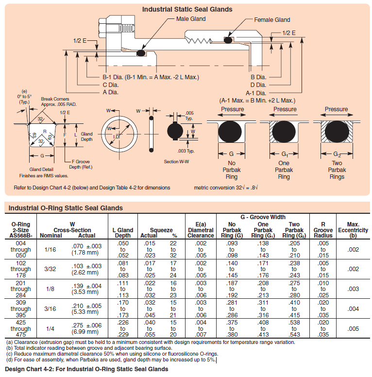
Basic Applications Metric ORing Groove Design Reference
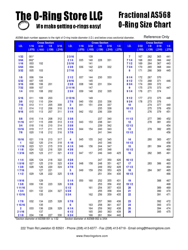
Printable O Ring Size Chart
O Ring Groove Size Chart

O Ring Groove Size Chart
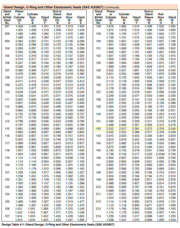
O Ring Groove Dimensions Chart

Oring Groove Size Chart
O'ring Groove Size Chart

o ring groove size chart pdf Ranee Ojeda
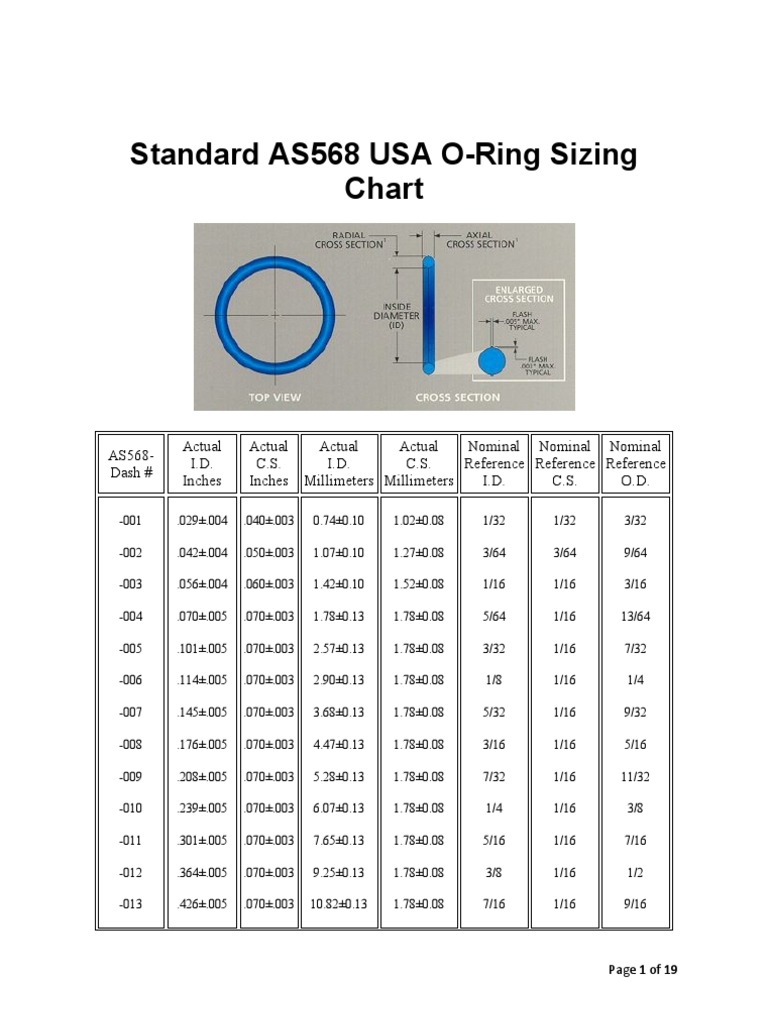
Standard AS568 USA ORing Sizing Chart

O'ring Sizing Chart
Radial And Dynamic Seals Require The Presence Of A.
Web 10| Measurements In Millimeters Measurements In Inches Id± ±± Csid ±± Idcs ±± Csid ± 37.60 0.09 39.60 2.40 41.60 44.60 0.44 45.60 47.60 49.60 51.60 2.40 54.60 55.60 0.094 57.60
The Guidelines Are For The Nominal Condition.
The Calculator Takes All Relevant Parameters Into Account Like:
Related Post: