Countersink Dimensions Chart
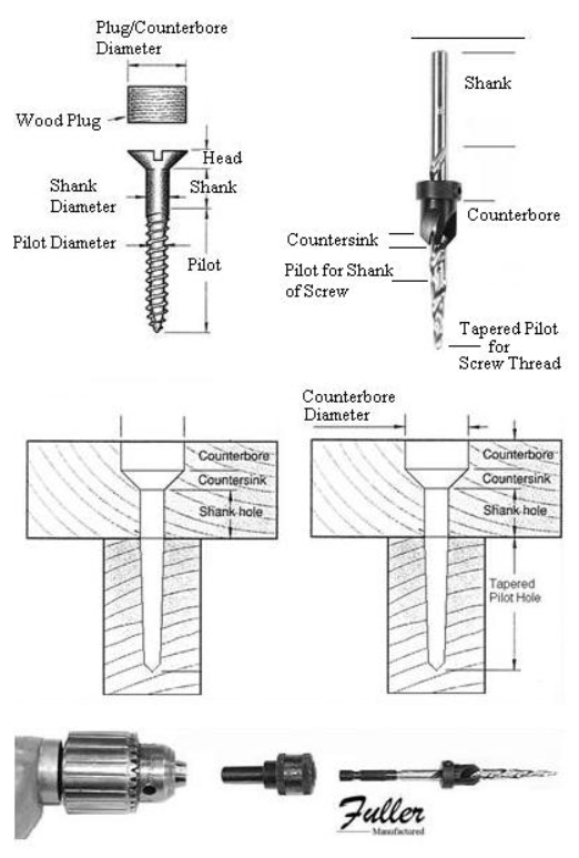
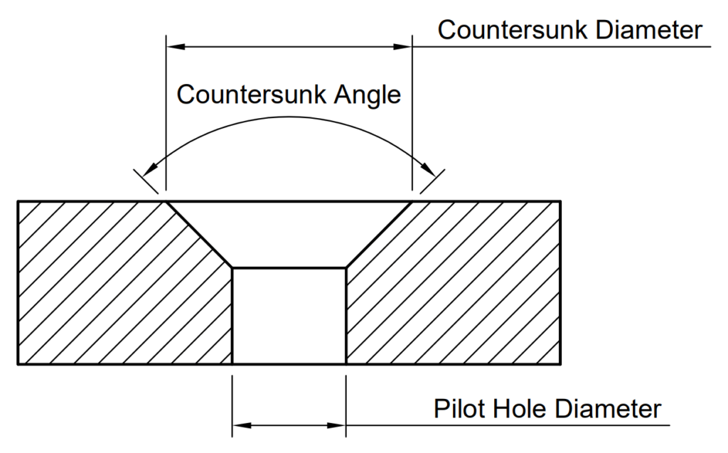
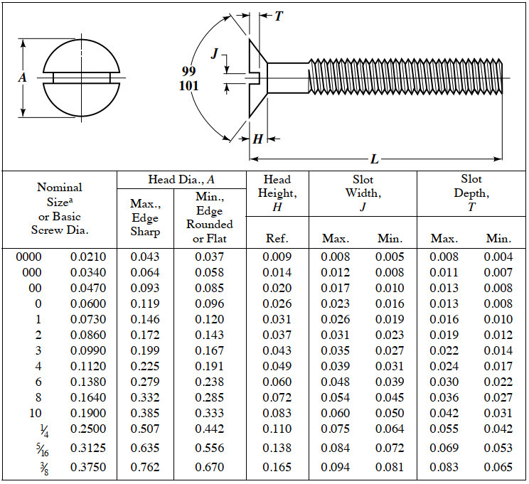
Countersink Dimensions Chart - Web use the image and chart below to determine what dimensions to use, all dimensions are in inches apart from the countersink angle. A screw placed in a countersunk hole is located by the angle. In the above example, the part has a 0.5 thru hole and a countersink with a. Web use the image and chart below to determine what dimensions to use, all dimensions are in millimetres apart from the countersink angle. Countersink depth is typically measured from the surface of the material to the bottom of the countersink hole. Web the graphic above shows how to fully define a countersink — the 3 dimensions needed to properly define a countersink are: Web this chart shows the dimensions of counterbore and countersink holes for different screw sizes, in metric units (millimeters). Web use the image and chart below to determine what dimensions to use, all dimensions are in millimetres apart from the countersink angle. Web unsure on what size countersunk hole to use for your ansi inch socket flat head fasteners? Web please note that this chart provides general guidelines and recommended dimensions. First, you must select the screw size you're working with (see the left side of the chart). Over 1” over 2 1/2” diameter to 1” to 2 1/2” to 6”. Web unsure on what size countersunk hole to use for your ansi metric socket flat head fasteners? Web use the image and chart below to determine what dimensions to use,. Web use the image and chart below to determine what dimensions to use, all dimensions are in millimetres apart from the countersink angle. In the charts that follow, the theoretical sharp diameter represents the diameter of countersink that will place maximum material condition screwhead flush to the surface of a flat part. Web when determining what are countersink holes, it. Web countersink depth is the depth of a countersink hole, which is a conical hole cut into a material to allow the head of a countersunk screw or bolt to be flush with or below the surface of the surrounding material. A screw placed in a countersunk hole is located by the angle. However, it is always essential to consult. Understand the types and use of countersink drill bit, countersink vs counterbore hole and check out the countersink size chart for holes/bits. In the above example, the part has a 0.5 thru hole and a countersink with a. Web use the image and chart below to determine what dimensions to use, all dimensions are in millimetres apart from the countersink. This short post will give you the exact dimensions you need for your countersunk screws. What controls the location of the screw? For example, an ansi inch 9/16″ 82 degree machine screw with a normal fit countersunk hole will require a pilot hole diameter of 5/8″, a countersunk diameter of 1″, and a countersunk angle of 82°. In the above. Web use the image and chart below to determine what dimensions to use, all dimensions are in millimetres apart from the countersink angle. First, you must select the screw size you're working with (see the left side of the chart). This is the nominal diameter of the countersink for the fastener. In the above example, the part has a 0.5. Web please note that this chart provides general guidelines and recommended dimensions. Web this chart shows the dimensions of counterbore and countersink holes for different screw sizes, in metric units (millimeters). However, it is always essential to consult the specific fastener manufacturer’s guidelines and reference the appropriate standards for accurate countersunk hole dimensions. Web unsure on what size countersunk hole. Understand the types and use of countersink drill bit, countersink vs counterbore hole and check out the countersink size chart for holes/bits. In the charts that follow, the theoretical sharp diameter represents the diameter of countersink that will place maximum material condition screwhead flush to the surface of a flat part. Web unsure on what size countersunk hole to use. Web please note that this chart provides general guidelines and recommended dimensions. This is the nominal diameter of the countersink for the fastener. Web controlled angle under the head ensures maximum flushness and side wall contact. Web use the image and chart below to determine what dimensions to use, all dimensions are in millimetres apart from the countersink angle. For. Web please note that this chart provides general guidelines and recommended dimensions. Understand the types and use of countersink drill bit, countersink vs counterbore hole and check out the countersink size chart for holes/bits. First, you must select the screw size you're working with (see the left side of the chart). It is considered good practice to countersink or break. This short post will give you the exact dimensions you need for your countersunk screws. Web countersunk socket head screws metric. This short post will give you the exact dimensions you need for your countersunk screws. Web how the show and chart below to determine how dimensions to using, show dimensions are inches millimetres apart from the countersink angle. Web unsure on what size countersunk hole to use for your ansi metric socket flat head fasteners? Web a countersink is dimensioned by specifying the diameter of the countersink where it meets the surface and the included angle. Web use the image and chart below to determine what dimensions to use, all dimensions are in inches apart from the countersink angle. In the above example, the part has a 0.5 thru hole and a countersink with a. This is the nominal diameter of the countersink for the fastener. Web sheet metal countersink chart. For example, an ansi metric m4 machine screw with a normal fit countersunk hole will require a pilot hole diameter of 4.5 mm, a countersunk diameter of 9.4 mm, and a countersunk angle of 90°. Controlled angle under the head ensures maximum flushness and side wall contact. Web controlled angle under the head ensures maximum flushness and side wall contact. Web countersink depth is the depth of a countersink hole, which is a conical hole cut into a material to allow the head of a countersunk screw or bolt to be flush with or below the surface of the surrounding material. Web just as with counterbore and spotface hole features, dimensions for a countersink are also listed directly below the dimension of the smaller coaxial hole. Nbrak u ohead markings may vary slightly depending on manufacturing practice.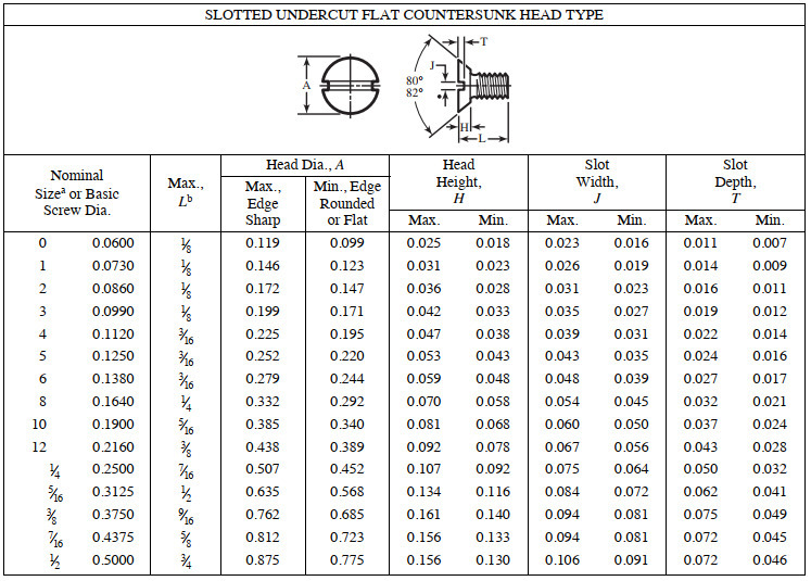
Standard Countersunk Hole Diameters Home Interior Design
Countersink drill size chart Jamestown Distributors

Countersink Drill Size Chart Drill, Chart, Home improvement

Countersink Size Chart Flat Head
Countersunk Hole Size for Machine Screw (ANSI Metric)
Metric Countersunk Hole Sizes Home Interior Design
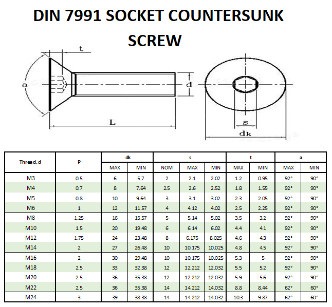
DIN 7991 Dimensions Beacon Corporation
Metric Countersink Dimensions Chart
Counterbore and Countersink Dimensions Chart
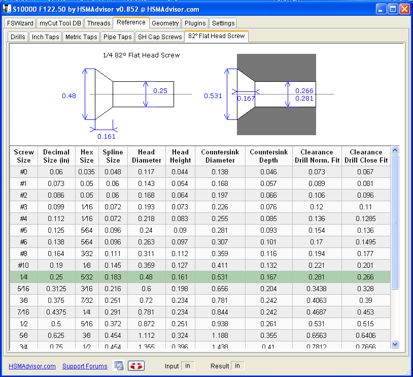
HSM Machining
What Controls The Location Of The Screw?
Over 1” Over 2 1/2” Diameter To 1” To 2 1/2” To 6”.
For Example, An Ansi Inch 9/16″ 100 Degree Machine Screw With A Normal Fit Countersunk Hole Will Require A Pilot Hole Diameter Of 5/8″, A Countersunk Diameter Of 1 10/69″, And A Countersunk Angle Of 100°.
Choose From A Variety Of Standard Countersink Options, Which Can Either Be Formed Or Machined Into Sheet Part Parts.
Related Post:
