Admittance Smith Chart
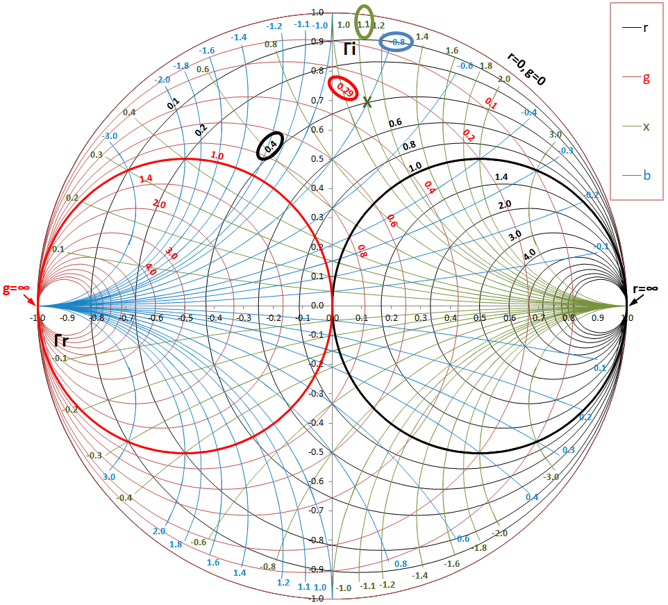
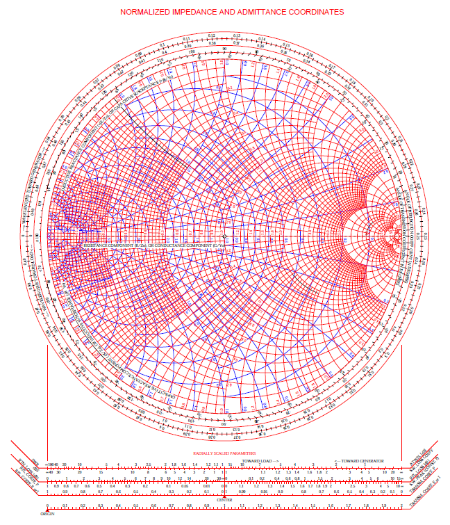
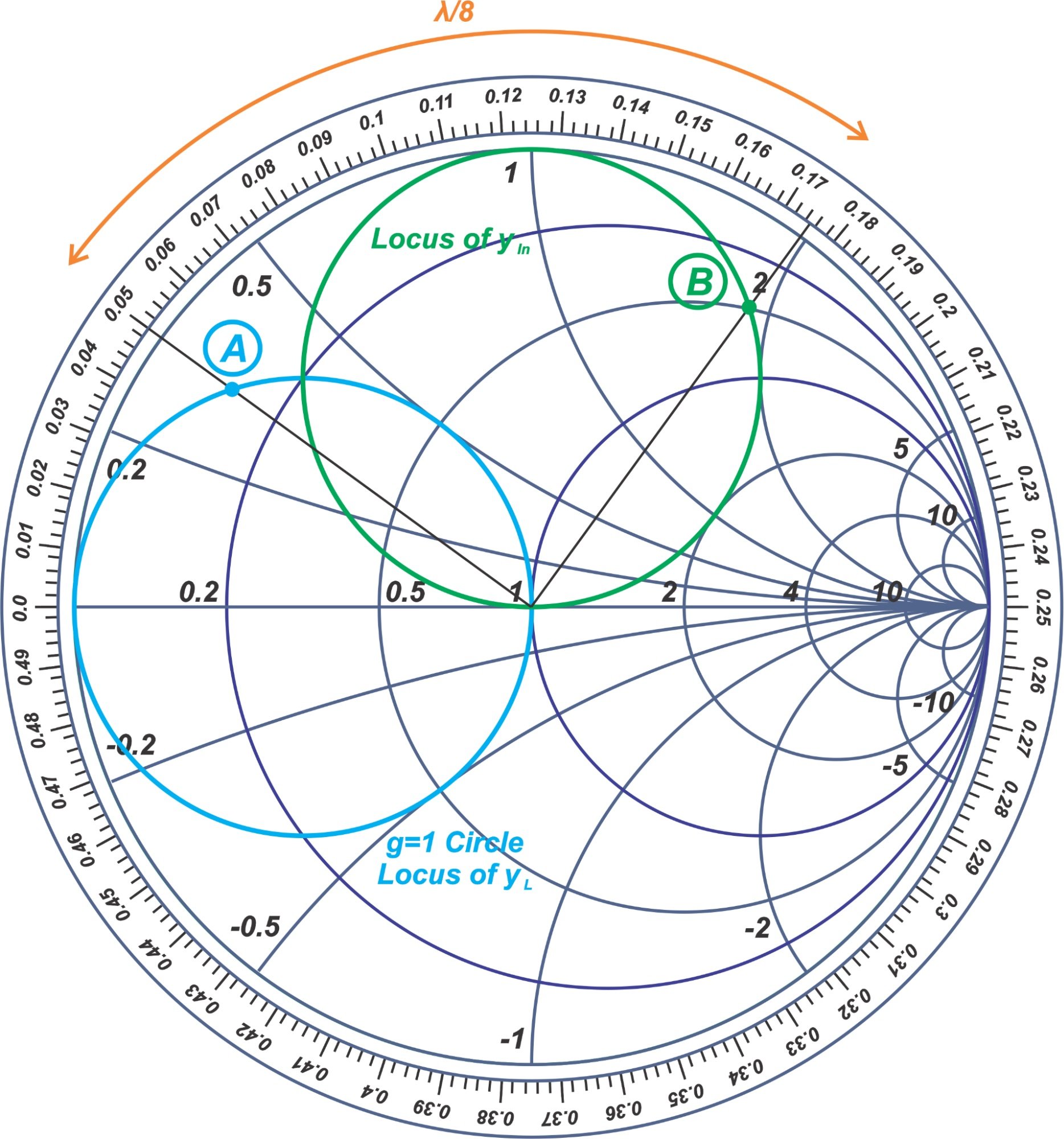
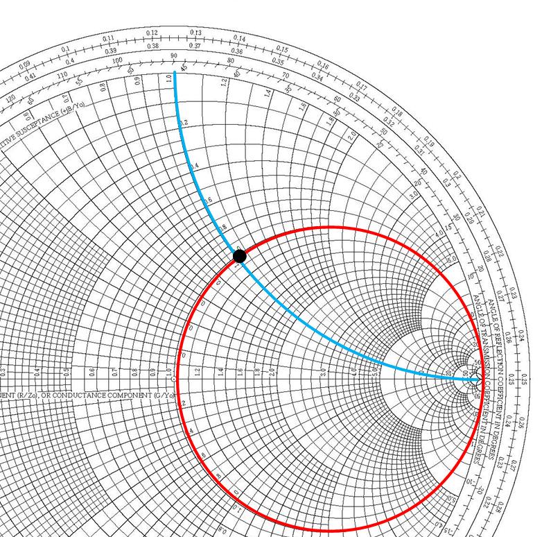
Admittance Smith Chart - Smith in 1939 and has since become a fundamental tool for electrical engineers working with. Impedance of a coaxial transmission line. The normalized impedance has a real and imaginary part zl = rl + jxl z l = r l + j x l, and the reflection coefficient can also be shown in cartesian coordinates as γ = γr + jγi γ = γ r + j γ i. Thus, we can locate the impedance z = 6 +. This smith chart, while it looks like chaos, is extraordinarily helpful. Web the smith chart works with normalized impedance and admittance, where normalization is made with respect to the characteristic impedance of the transmission line. Web a smith chart is commonly used to display the relationship between a reflection coefficient, typically s11 or s22, and a normalized impedance. Web 0.1 0.1 0.1 0.2 0.2 0.2 0.3 0.3 0.3 0.4 0.4 0.4 0.5 0.5 0.5 0.6 0.6 0.6 0.7 0.7 0.7 0.8 0.8 0.8 0.9 0.9 0.9 1.0 1.0 1.0 1.2 1.2 1.2 1.4 1.4 1.4 1.6 1.6 1.6 1.8 1.8 1. Web the smith chart is a powerful graphical tool that is extensively used by rf engineers to rapidly determine how a given impedance can be transformed into another one. Web the smith chart provides a graphical representation of γ that permits the determination of quantities such as the vswr or the terminating impedance of a device under test (dut). Web the smith chart can be used to simultaneously display multiple parameters including impedances, admittances, reflection coefficients, scattering parameters, noise figure circles, constant gain contours and regions for unconditional stability. Web the smith chart was invented by phillip smith in 1939 in order to provide an easily usable graphical representation of the complex reflection coefficient γ and reading of the. Web the smith chart is a polar plot of the complex reflection coefficient (also called gamma and symbolized by γ). Web the smith chart is a sophisticated graphic tool for solving transmission line problems. Web admittance on the impedance smith chart. Impedance and reflection coefficient are complex numbers. These graphs are used for visualizing the impedance at any point on. Web 0.1 0.1 0.1 0.2 0.2 0.2 0.3 0.3 0.3 0.4 0.4 0.4 0.5 0.5 0.5 0.6 0.6 0.6 0.7 0.7 0.7 0.8 0.8 0.8 0.9 0.9 0.9 1.0 1.0 1.0 1.2 1.2 1.2 1.4 1.4 1.4 1.6 1.6 1.6 1.8 1.8 1. These graphs are used for visualizing the impedance at any point on the transmission line or any. First, we express the load = 6 + j 2. Impedance and reflection coefficient are complex numbers. Web 3.4.2 admittance smith chart. The smithplot function replaces the smithchart function. For example, the normalized impedance for a load zl = 73 + j42. This smith chart, while it looks like chaos, is extraordinarily helpful. Admittance y ′ = z. 6 in terms of its. A less dense form is shown in figure \(\pageindex{8}\)(a). Web the immittance smith chart. Web the smith chart was invented by phillip smith in 1939 in order to provide an easily usable graphical representation of the complex reflection coefficient γ and reading of the associated complex terminating impedance. Web impedance matching and smith charts. Admittance smith chart recall that on the standard or impedance smith chart, the circles and curves related to constant resistance. Web definition of the smith chart, mapping the complex impedance / admittance plane with the complex reflection coefficient. The smith chart above shows both the impedance mapping (red) and admittance mapping (blue). Web a smith chart is commonly used to display the relationship between a reflection coefficient, typically s11 or s22, and a normalized impedance. The goal is for the. A smith chart is developed by examining the. Web 0.1 0.1 0.1 0.2 0.2 0.2 0.3 0.3 0.3 0.4 0.4 0.4 0.5 0.5 0.5 0.6 0.6 0.6 0.7 0.7 0.7 0.8 0.8 0.8 0.9 0.9 0.9 1.0 1.0 1.0 1.2 1.2 1.2 1.4 1.4 1.4 1.6 1.6 1.6 1.8 1.8 1. Web the smith chart can be used to simultaneously. 6 in terms of its. Admittance smith chart recall that on the standard or impedance smith chart, the circles and curves related to constant resistance and constant reactance. The admittance smith chart has loci for discrete constant susceptances ranging from \(−∞\) to \(∞\), and for discrete constant conductance ranging from \(0\) to \(∞\), see figure \(\pageindex{7}\). It is made of. Admittance smith chart recall that on the standard or impedance smith chart, the circles and curves related to constant resistance and constant reactance. This chart looks like the flipped version of the. Impedance z has real resistance r and imaginary reactance x : It uses a bilinear moebius transformation, projecting the complex impedance plane onto the complex γ plane: The. This section first presents the impedance smith chart and then the admittance smith chart before introducing a combined smith chart which is the form needed in design. Web impedance smith charts also known as z charts are the polar graphs that show the normalized line impedance in the complex reflection coefficient plane. A smith chart is developed by examining the. But it is just the admittance smith chart in red overlayed on top of the impedance smith chart in green. Web admittance on the impedance smith chart. The normalized impedance has a real and imaginary part zl = rl + jxl z l = r l + j x l, and the reflection coefficient can also be shown in cartesian coordinates as γ = γr + jγi γ = γ r + j γ i. Web 3.4.2 admittance smith chart. Simple rules of smith chart tuning will be presented, followed by examples. Web the smith chart works with normalized impedance and admittance, where normalization is made with respect to the characteristic impedance of the transmission line. Web the smith chart is a graphical representation of complex impedance and admittance. L this complex value—or we can use a smith chart! The parallel capacitor affects only the susceptance of the new admittance. Web 0.1 0.1 0.1 0.2 0.2 0.2 0.3 0.3 0.3 0.4 0.4 0.4 0.5 0.5 0.5 0.6 0.6 0.6 0.7 0.7 0.7 0.8 0.8 0.8 0.9 0.9 0.9 1.0 1.0 1.0 1.2 1.2 1.2 1.4 1.4 1.4 1.6 1.6 1.6 1.8 1.8 1. Web to generalize the smith chart and to make things easier for parallel impedance matching, we will now introduce the admittance smith chart. These graphs are used for visualizing the impedance at any point on the transmission line or any input in the systems of the antenna. The reflection coefficient can be found from impedance or admittance.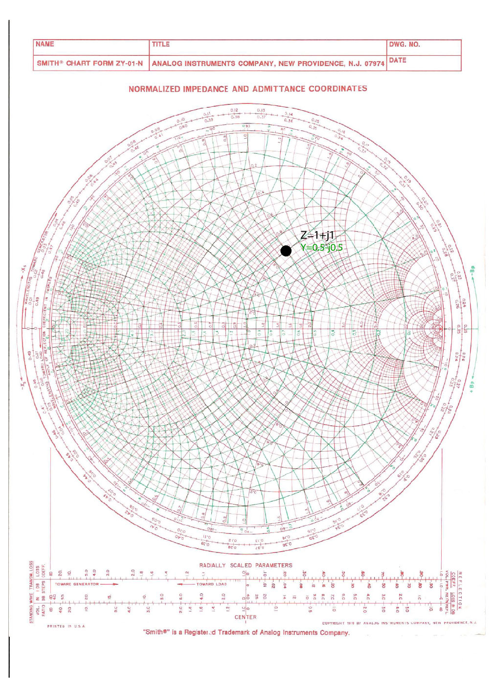
Impedance and Admittance on Smith Chart Ximera

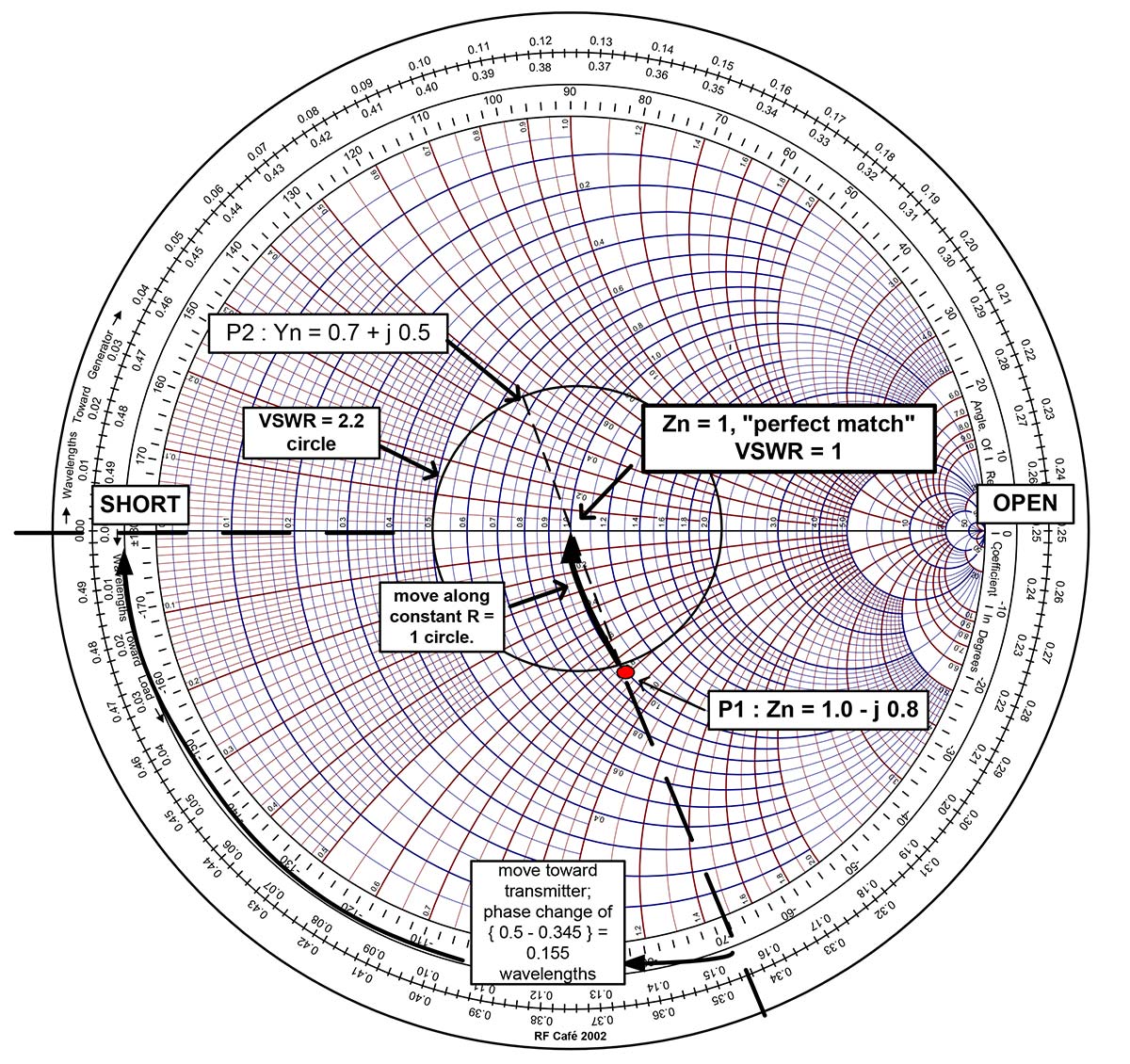
Impedance Matching by Using Smith Chart A StepbyStep Guide, Part II
Smith Chart Fundamentals Nuts & Volts Magazine

The Complete Smith Chart
Impedance Matching by Using Smith Chart A StepbyStep Guide, Part II
Impedance and Admittance on Smith Chart Ximera
Smith chart impedance and admittance startguides
What is Smith Chart and how to use it for Impedance Matching
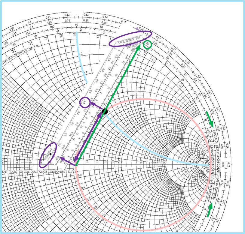
Learn Stub Tuning With a Smith Chart Technical Articles
Impedance and Admittance on Smith Chart Ximera
With Z = R + J X.
Thus, We Can Locate The Impedance Z = 6 +.
This Chart Looks Like The Flipped Version Of The.
Admittance Smith Chart Recall That On The Standard Or Impedance Smith Chart, The Circles And Curves Related To Constant Resistance And Constant Reactance.
Related Post: